Week 6: 3D scanning and printing
Group Assignment: characterizing the 3D printers
3D designing
For this weeks assignment we where not allowed to download a 3D-design. We had to draw, model, design something ourselves. My idea about my final project is leaning more and more to building a model of a sensory hair cell. It is just an amazing kind of cell with it's hairlike villi dat move on the motion of inner ear fluid and in reaction to that, mechanically open ion-gates that change the cells electric potential. On top of that I have a daughter that is partially hearing impaired, so it also has symbolic value for me.
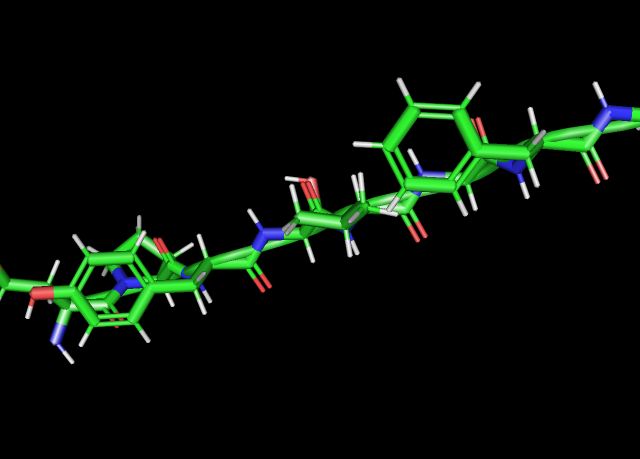
My first idea therefore was to draw the proteïn that mechanically opens this ion-gate in the hair cell villi. You can find a great image of this protein here on the website of The Theoretical and Computational Biophysics Group of the University of Illinois. Allthough eventually I had to let go of this idea, it has been a very informative journey.
searching for the right proteïn
So I started a search for this proteïn. I found this site of the Center of Macromolecular Modelling and Bioinformatics of the University of Illinois that is very informative on the subject of the moleculair base of hearing. The proteïn to search for was Ankyrin, I learned. I actually found the proteïn, or at least a repetative part of it on Thingiverse. Amazing. Off course I was not alowed to just print this file, I tried to draw it myself.
trying to draw a proteïn
I opened Fusion and on YouTube looked for a tutorial to draw helixes or at least a coil. I found a video that at the moment of updating my documentation was deleted. The problem with Fusion360 is that it doesnt let you choose the form you want to build the coil with. You can choose a circle, a triangle and a square, but no free form. The workflow I followed to work around this is on the left down here. In the middle is the result. This is so far from what it should be, on the right, and besides that, I have no idea what angle the different strings and helices are positioned relative to eachother. It got me discouraged and I dropped the idea of drawing a protein myself.
New sketch, create coil, new sketch, draw elips, coincide the elips to the edge of the coil, sweep, choose the edge of the coil as a path, delete the coil 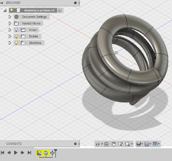
trying to model a proteïn with PyMol
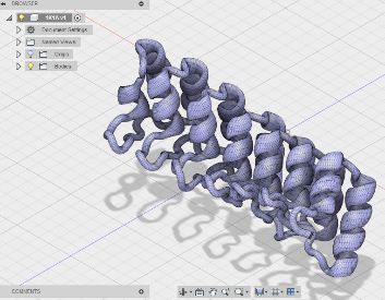
Then I got the idea to model the protein myself from, for instance an amino accid sequence. I found an amino accid sequence here. It is a sequence for a iso form of Ankyrin. I don't know what it means exactly. Maybe it has something to do with stereo chemistry. On YouTube I found some sort of instruction of someone modelling proteïns with a program called PyMol. I downloaded this program and tried to use it. First I tried to just add the amino accid in the sequence I found. After 8 aminoaccids, the left picture is the result. Hundreds of amino accids to go and no clue of what to do to get a usable 3D file. I dropped this strategy. From the search for the proteïn I learned that proteïns and polypeptides are characterized in a global Protein Databse and have a corresponding PDB-id. I found out that the PDB-id for a 12 repeat of human Ankyrin-R is 1N11. PyMol has a function called 'get PDB'. So I tried that. Unfortunately PyMol crashed on this two times. On top of that, if you use the educational version of PyMol, you are not allowed to share your designs on a website. So I said goodbye to PyMol
drawing a chainmail in Fusion 360 using parameters
And now for something completely different. The interesting thing about proteïns, and the folding of amino accids in particular, is that form and physiology determines its function. The Ankyrin protein functions as a molecular spring. Material behaving in a different manner under different conditions, because of scaling, folding etc, I find fascinating. This is what got me the idea of drawing a fabric kind of design in Fusion 360.
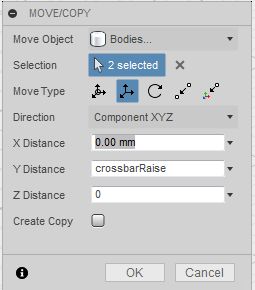
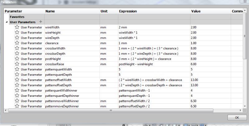
I found a great tutorial on YouTube called Make chainmail in Fusion 360. Offcourse I stumbled on a problem, following this tutorial. It was due to the fact that the instructor is drawing on the XY plane and I was drawing on the XZ plane. First I tried to work around this by changing all the Y-parameters for the Z-parameters. For instance shown in the left picture; the crossbar-parameter is put on the Z-axis in the tutorial. But eventually this didn't work out, it got me confused. So I started all over again. In the right picture you find all the parameters I used for my final design. I will explain why I chose these particular dimensions later on, in the section on 3D-printing.
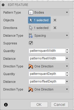
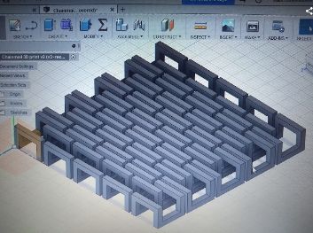
I learned a great deal more about using parameters in fusion 360. For instance that under Model Parameters (found under the menu of changing parameters, the sigma-sign) you can see all the parameters you used in different modifications of your design. You can also change them there. An example is shown in the picture on the left. I also learned about making a rectangular pattern as shown in the middle. Be sure you choose a new direction when filling in the quantity and spacing for the second direction. Otherwise Fusion 360 wil choose a default direction and you end op with a pattern of links stacked on top of eachother instead of spread out on the plane. On the right is a picture of my final design. To export the file as STL in fusion 360 you right click on the name of your file in the left menu (where you alo find origin,bodies, sketches etc.) and chose save as STL. This is the filetyp Cura can use to make Gcode; a code that tells the 3D printer what paths to take extruding the filament. You can use the button under here to download the final STL file.
STL file chainmail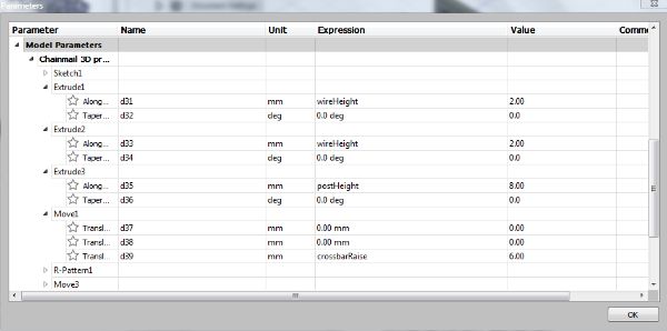
3D printing
After saving my file as STL,it was time to open it in Cura. On this page I downloaded Cura foor BCN3D sigma, the printer I was going to use. I chose this printer because it had the best performances on the characterisation of the three 3D printers in the Amsterdam Fab Lab. From the results of the printing of the templates I saw that printing an overhang of 8 mm should't be a problem. That is why I set the crossbarhight and crossbardepth of the links in my chainmail to 8 mm.preparing the file in Cura
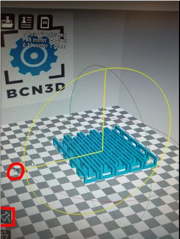
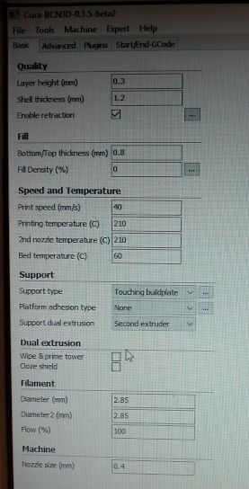
When you open Cura foor BCN3D sigma, you chose 'load model file' in the file menu on the top left. My file came up vertically, so first I turned using the corresponding icon on the right. You can see this in the left picture down here. After this I filled in the settings under 'Support' as pictured on the right, and left the rest at default.In the middle are the settings I changed, just in case you cannot read it.I saved the file as Gcode with the save icon on a SD card that can be inserted in the printer.
- Support type: touching build plate;
- Platform adhesion type: brim;
- Support dual extrusion: second extruder
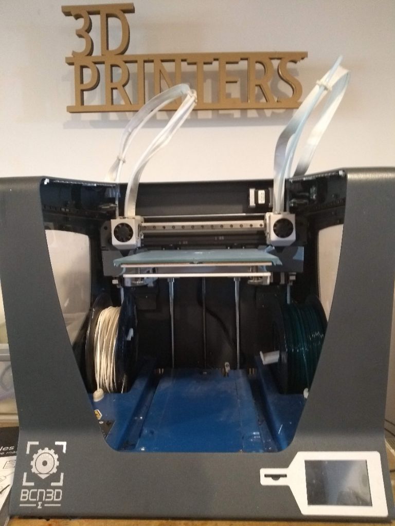
preparing the BCN3D Sigma
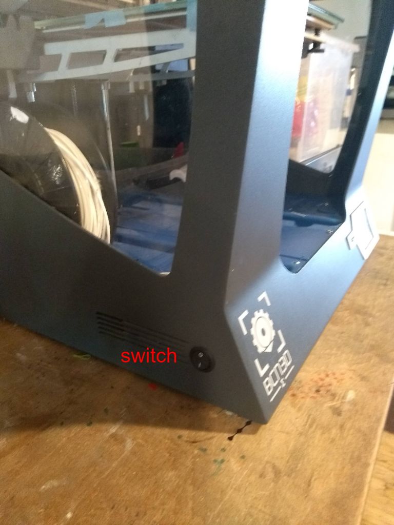
I inserted the SD card in the machine, left of the display in the front. After that I turned on the machine. The switch is on the left side of the machine.
unloading
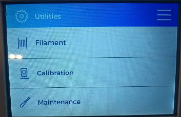
The first thing to do is to unload the filament that is currently in the machine. (If you want a different filament) Under Utilities in the display, you choose filament and unload. Also choose the nozzle you want to unload. The machine guides you through the unloading proces. You remove the filament by turning the spool while the printer withdraws the filament. Now you can take out the spool.
loading
You take the spool with the filament you want to use. First you cut of the tip of the filemant to a sharp point. Then you put in the filment in the white opening until you can push no further. Press Load under Utilities and Filament, also choose the nozzle you want to load and the type of filament (PLA). The machine will guide you through the loading process. At the end you press extrude untill the new filament colour comes out of the nozzle. If the machine failes to take up the filament, you can do it manually by pressing a pinch right under the nozzle motor and at the same time pushing the filament.
calibrating the bed
Now it is time to calibrate the bed. Under the Utilities menu Calibration and after that Bed Calibration. The bed is calibrated with two screws. The machine wil tell you which screws to turn in which direction. This is something you repeat a few times until the machine tells you: Succes!
selecting the file
In the display you press Print. Then you select your file from the SD card. Press accept and of it goes!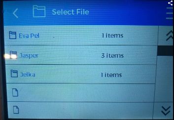
speed reduction in the first fase
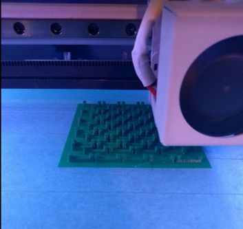
Off course the first print went boink. In the back right corner the brim didn't stick tot the bed. The result is seen in the left picture down here. So I started the print over and changed the speed to 65%. When the brim was nicely put on the bed, I changed the speed to 80% and when I was confident about the first layers I set the speed to 100%. All went wel as you can see in the picture on the right.
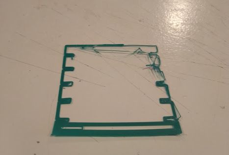
removing the print and peeling the brim
Hurray! the resulting print looked perfect. No problems with the overhangs. I peeled of the print with a spatula. This went wel. But then I started peeling of the brim from the print in a way to rough manner. I wrecked my print!
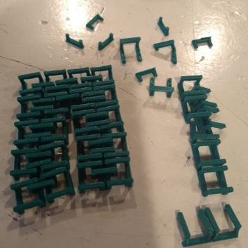
soldering the result
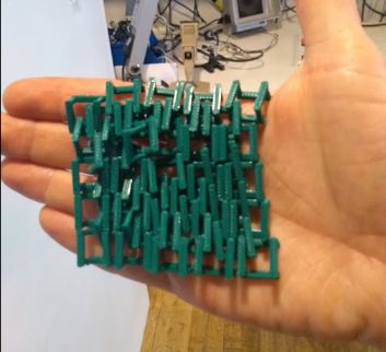
Cecilia from the Fabricademy proposed to solder the broken links together again. It wasn't easy, but I managed quite wel.
The result
Intentions for the next time
Next time I will peel off the brim with more caution. Also I would really like to design another chainmail with different kind of links.
3D scanning
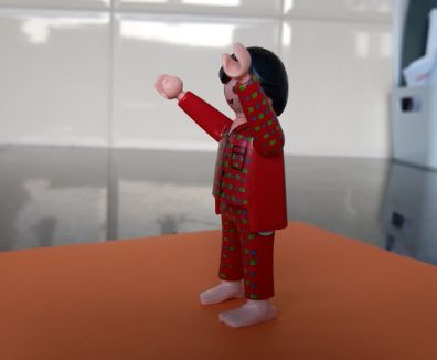
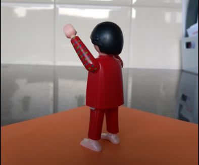
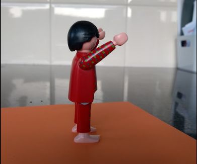
I used the Sense for 3D scanning. I couldn't really think of something usefull to scann, so I decided to scan some Playmobil or My Little Pony figures. The Sense is a very easy to use 3D scanner. You can find a tutorila on unboing, installation and use here. I plugged it in the 3.0 USB-port (the blue one!)of the computer it is running on in the lab. On the computerscreen I clicked the Sense-software icon in the menu bar at the bottom. It has three options; object, body or.. I was going to scan an object. So I chose that.
I figured it would be easier to revolve the figure itself then turning the scanner around it. So I sticked the Playmobil figure on a piece of paper using double sided tape. I clicked Scan, then the program counts down from 3 to 1. Then I started turning the paper around. I didn't work. Constantly it was losing track and I had turn the figure back to a previous position. First of all this might be because the Sense is programmed to move itself. It probably makes corrections for it's own motion. There might be some motion sensors in there. Second the Playmobil figure is probably to small.
So I tried scanning my hand. For this I chose Object again in the Sense software. Just because I forgot to change it to Body. But it worked quite well. I tried to turn the Sense around my hand as far as I could. 360 degrees was not possible offcourse. But is you revolve around your hand along two different axes; horizontally and vertically, it does a nice job. While it was scaning my hand it only displayed half of my hand in the white-greenisch representation (indicating that it has made a good scan of that part of the object) but the image turned out pretty okay. When you are done, click Finish. Or ask someone to do it for you, because you have your hands full. Sense will tell you it is applying some magic. And then you are good to go and save the file with an obj extension. You can download my zipped obj image down here
OBJ file hand scan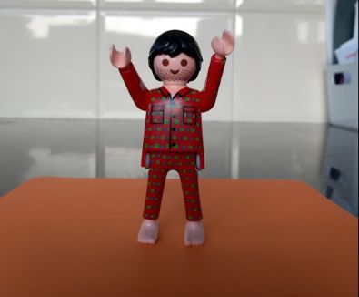
Refining the OBJ file with meshmixer
I downloaded Meshmixer from this site. And then I tried to run it. It gave me this error instantly.
In may I tried again with a new laptop. Downloading and installing Meshmixer went fine. I imported my file, deleted the messy bits and made it a solid. There could be much more things that you can do, but at this point, with so much time spent on this assignment, I will leave it at this. You can download my edited file here:
Meshmixer tutorial
- Open meshmixer
- Click import in the top left corner
- Click Append
- Choose your dimensions for scaling
Edit
- Transform
- Click on the Axis you want toen move it on and scroll your mouse
- Click accept
Erase a part of the object
- Select
- Draw a line across the object dragging the mouse while pushing the left button. It will select one of the parts.
- Click erase and fill
Add limbs
- Click meshmixer on the top left
- Click and drag a limb of your choosing to the object.
- Don’t click Accept yet
- You can turn it around, move it and scale it.
- When you are satisfied, click accept.
Smoothing
- Click on Sculpt
- Brushes
- Choose a brush of your liking
- Adjust the size of the brush
- Hover over the object while left clicking the mouse
Make ready for printing
- Edit
- Make solid. (After this you can still edit, like smoothen)
- Analyse the object by clicking on Analysis
- Left click on inspector
- Auto repair
- Export
- Select a folder
- Create a name
- Save as obj